The circuit
The circuit consists of two parts: a pre-amplifier and the detector itself (Click the images to see them in full size).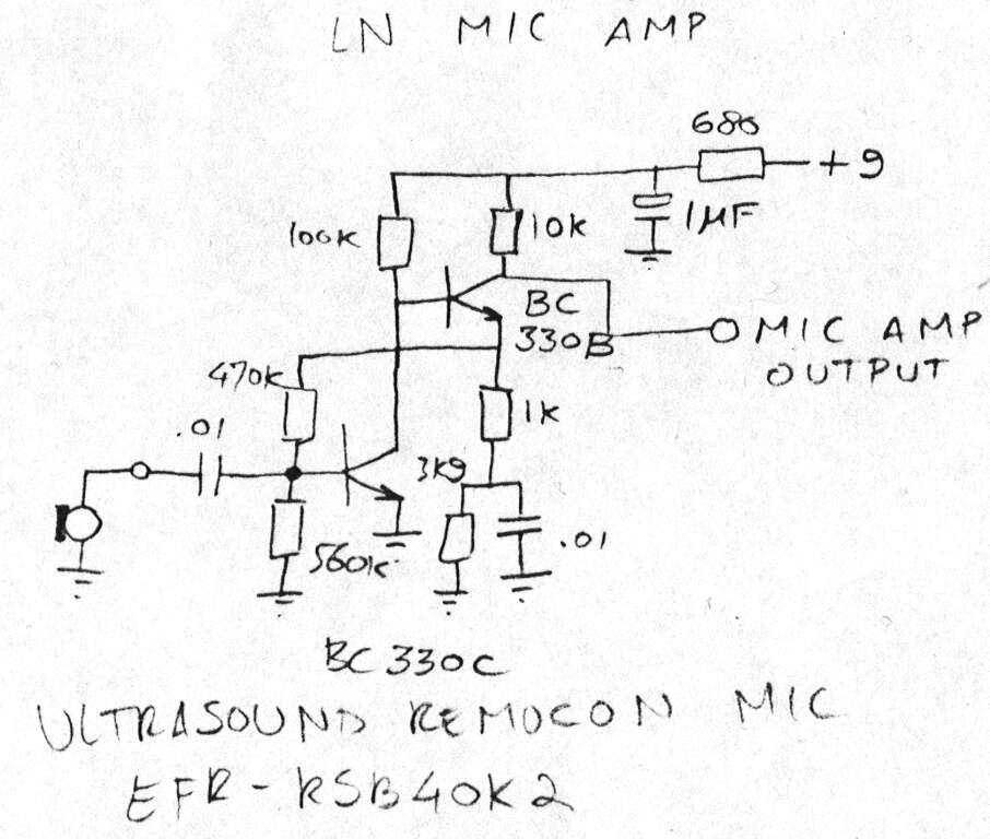
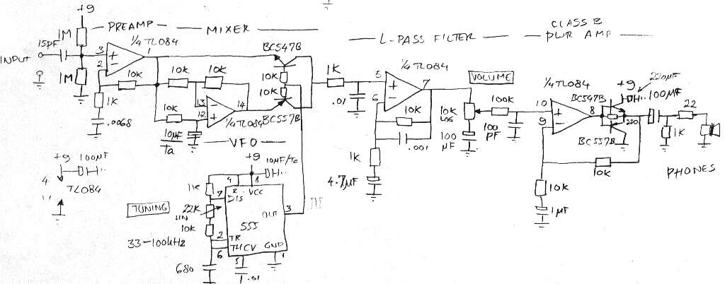
My explanation of the circuit
Pre-amplifier
The pre-amplifier consists of two transistor stages.The transistor on the left runs at very low current and provides most of the gain. The other transistor provides some gain and buffers the signal, giving an output impedance of about 10k.
Detector
The detection principle in this circuit is direct conversion by means of a switching mixer.Going from the left to the right, we first see an amplifying and buffering opamp stage. This opamp is biased to half the supply voltage by means of the two 1 megaohm resistors. It has a gain of about 10 times.
The next part of the circuit is the switching mixer. The opamp in this mixer inverts the bat signal (i.e. gain of -1). The transistors do the actual multiplication of the bat signal with the oscillator signal, by alternatively conducting the inverted or non-inverted bat signal.
The oscillator signal is a square wave, generated by the 555 in its familiar astable configuration.
The multiplied signal now contains the desired difference frequency and the undesired sum frequency component. The latter is removed by means of the second order low-pass filter.
The last stage is a power amplifier.
This page was last updated Saturday, June 24, 2000