Main homepage
mail me !
Also check out this pdf.
AM receiver circuit

Description
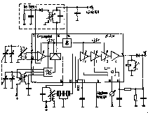
TCA 440 is a monolithic IC, especially developed for AM receivers up to 50 Mhz. It includes a RF stage with AGC, a balanced mixer, separate oscillator and an IF amplifier with AGC. Because of its low current consumption and of its internal stabilisation the TCA 440 is perfectly suited for battery operated portables, car and home radios.Tuning meter
Recommended instruments:500 micro-A (R1=800 Ohm) or 300 micro-A (R1=1.5 kOhm)
The IC offers at pin 10 a tuning meter voltage of 600 mV-EMP max. with a source impedance of approx. 400 Ohm.
Function
As pictured in the circuit diagram the TCA 440 comprises two control loops independent of each other which control the RF stage amd the IF stages. By AGCing the RF stage, excellent signal handling is obtained. A voltage of 2.6 Vpp on the IC input can be handled with very low distortion. The push-pull mixer operates multiplicatively, thereby resulting in few harmonic mixing products and whistling points. The oscillator which is separated from the mixer is also apted excellently for short waves. From the AGC of the RF amplifier a voltage is derived for a tuning meter which can be connected directly to the meter. The symmetric composition of the circuit provides high stability against oscillation and, at the same time, an AGC range of more than 100 dB. The bridge circuit provides good isolation of the oscillator.Absolute maximum ratings
| Vcc | Supply voltage | 15 | V |
| Tamb | Ambient temperature in operation | -15 to +80 | deg. C |
| Ts | Storage temperature | -30 to +125 | deg. C |
| Vcc | Range of operation | 4.5 to 15 | V |
Features
- Balanced circuit
- Separately controllable prestage
- Multiplicative push-pull mixer with separate oscillator
- High signal handling capability even with 4.5 V supply voltage
- 100 dB feedback control range in 5 stages
- Direct connection for tuning meter
- Minimum external components
PIN CONFIGURATION
N package| RF input | 1 | 16 | Mixer output | |
| RF input | 2 | 15 | Mixer output | |
| AGC RF stage | 3 | 14 | Supply | |
| Multiplier input | 4 | 13 | IF decouple | |
| Multiplier input | 5 | 12 | IF input | |
| Oscillator | 6 | 11 | IF input | |
| IF output | 7 | 10 | Meter output | |
| Ground | 8 | 9 | AGC IF stage |