HV circuits
Electrostatic microphones are just sound-sensitive capacitors that translate sound through small capacitance variations into small voltage variations. They work best when they are biased to a high voltage, which is typically between 50V to 300V.Some special requirements need to be met for use in a bat detector, like:
- Low current consumption (we are running on battery power)
- Little interference
- Preferably small
- Diode-capacitor voltage multiplier.
- Flyback-circuit.
By quickly shutting off the current through a coil, it will generate a voltage peak that can be captured in a storage capacitor. - Transformer circuit: either used in pulse-mode or continuous mode
Transformer circuit
 This is a pulse-mode transformer circuit that I have some experience with.
I used this successfully in combination with a Polaroid transducer.
Introduction
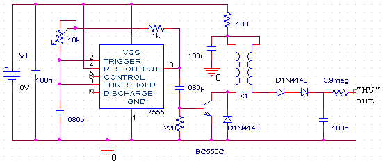
The circuit can be used to generate a voltage of about 70V using a current of about 4 mA @ 6V input voltage. The use of an easily available stroboscope trigger coil makes it quite small.How it works
The integrated circuit is a 7555 generating a 50/50 square wave of around 100 kHz. The square wave's rising edges momentarily trigger the transistor into conduction, causing current to flow through the primary of the stroboscope transformer. The current pulse in the primary causes a much larger voltage pulse in the secondary of the transformer, thereby charging the output capacitor through the diodes.Components
I'm using the 7555 (CMOS variety of the NE555) to generate the square wave, because it behaves much better with respect to power supply transients than the NE555. The circuit topology used here makes it possible to generate a 50% duty cycle square wave with only few external components (the resistors from output to treshold/trigger and the capacitor between treshold/trigger and ground).The type of transistor is not very important I think. I just used a BC550 because I had it available. On the rising edge of the square wave, the transistor is switched on through the capacitor. It is quickly switched off, because the capacitor discharges through the resistor between base and ground. I connected a diode across the transistor's emitter and collector, to protect it against the negative voltage spike from the primary winding.
 The stroboscope trigger coil is a 4 kV type, meaning that it is supposed to
convert a 300V pulse to 4 kV in its original application (a step-up ratio of about 13).
There are also 6 kV types available, perhaps they give better results.
The primary and secondary windings share a common connection,
hence there are only 3 wires instead of 4.
The 100 ohm resistor in series with the coil limits the continuous current,
while the capacitor connected to the coil makes sure that the
instantaneous current through the coil is not limited.
The stroboscope trigger coil is a 4 kV type, meaning that it is supposed to
convert a 300V pulse to 4 kV in its original application (a step-up ratio of about 13).
There are also 6 kV types available, perhaps they give better results.
The primary and secondary windings share a common connection,
hence there are only 3 wires instead of 4.
The 100 ohm resistor in series with the coil limits the continuous current,
while the capacitor connected to the coil makes sure that the
instantaneous current through the coil is not limited.The diodes I'm using are ordinary 1N4148 diodes (equivalent to 1N914). They have a breakdown voltage (reverse conduction voltage) of about 75V, so I used two in series, just to be sure.
The output capacitor is quite small at 100 nF. I haven't tried touching it yet when the circuit was operating, please beware of the high voltage. Shorting the capacitor give a nice little spark.
To connect the bias to the microphone, a resistor of several mega-ohms is used. The high resistance is no problem because the microphone doesn't draw any continuous current.
Interference and how to avoid it
The interference from this circuit can be pretty bad. Especially since this circuit will be used with a electrostatic microphone that needs a high-impedance pre-amplifier which is by its nature already very sensitive to interference.I found a very cool trick to avoid the interference: In case you're using a heterodyne detector, just use one oscillator for both demodulation and to trigger the transistor. The switching noise is now exactly synchronous with the oscillator and will be virtually eliminated.
This page was last updated Saturday, June 24, 2000